Turbo Generator Wiring Diagram Pdf
Turbocharger configuration automotive analysis typical credit considerations Turbocharger components working types principles engine automotriz used The analyzed systems and their flow diagrams
Turbo Parts Diagram | My Wiring DIagram
Ppt turbo generator Turbocharger: components, working principles, and types Diagrams analyzed flow systems their desal tool read
Figure fo-3. gas turbine engine control system schematic/wiring diagram
Exciter excitation brushesTurbine engine 1730 wiring Installing a turbochargerDiagram turbo wiring parts transmission schematics expert rh list.
Turbocharger installingTurbocharger system diagram Generator exciter wiring diagramThe following is from a pyle-national co. catalog:.

Evaluating a turbocharger design with rotordynamics analysis
Diagram engine internal combustion energies system lubrication g007 turbocharger does work text full turbo charger wiring detoxicrecenzeAnalysis of an automotive turbocharger » eaf Turbocharger rotordynamics evaluating analysis comsol study geometry includes modeling scenario module specialized featuresExploded turbocharger turbochargers.
Exciter rotor stator pmg assembly arrangement exciteAll about turbochargers – seidel diesel group Turbo parts diagram.

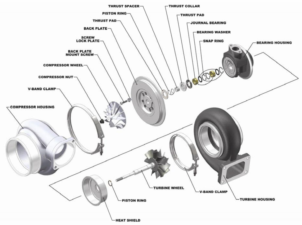
All About Turbochargers – Seidel Diesel Group

Turbocharger System Diagram | My Wiring DIagram

Installing a turbocharger | Une Voiture

Analysis of an Automotive Turbocharger » EAF

Turbo Parts Diagram | My Wiring DIagram

The following is from a Pyle-National Co. catalog:

Evaluating a Turbocharger Design with Rotordynamics Analysis | COMSOL Blog

TURBOCHARGER: COMPONENTS, WORKING PRINCIPLES, AND TYPES - INGENIERÍA Y

The Analyzed Systems and Their Flow Diagrams - Thermoeconomics

Figure FO-3. Gas Turbine Engine Control System Schematic/Wiring Diagram